This second article (in a series of 7 articles) reveals the technique used to 3D render the Generative Nano S Plus collection: using a GLSL fragment shader, without any 3D model, raymarching a calculated distance to a Nano S Plus.
Timeline:
- article 1: GNSP – the concept
- article 2: the 3D distance to a Nano S Plus
- article 3: the nano screen
- article 4: the swivel
- article 5: the background
- article 6: the video generation
- article 7: the final drop
- (?March) public mint
The collection is browsable on https://greweb.me/gnsp
OpenSea: https://opensea.io/collection/gnsp
The rendering is implemented in a GLSL Fragment Shader
The generative art is rendered entirely into one "fragment shader", which is essentially a GPU program that takes a bunch of inputs and efficiently calculates the pixel colors with your graphic card.
This is a paradigm I like to call "Functional Rendering paradigm": see article https://observablehq.com/@gre/introduction-to-functional-rendering-paradigm
On top of this paradigm, I have used a technique called Raymarching distance function, see article https://observablehq.com/@gre/introduction-to-raymarching-distance-functions
Here is the main algorithm that implement the raymarching: (where map is the distance function)
HIT marcher (inout vec3 p, vec3 dir) {
  HIT hit = HIT(0.);
  float t = 0.;
  for (int i=0; i<120; i++) {
    HIT h = map(p + t * dir);
    t += h.x;
    if (abs(h.x) < .0001) {
      hit = h;
      break;
    }
  }
  p += t * dir;
  return hit;
}
A fun proof of this is to play with the number of raymarching iteration (modulating iterations from 0 to 120):
The main scene is described in this "map" distance function:
HIT map (vec3 position) {
  HIT s = HIT(10. - length(position), 0.);
  float t = 3. * fract(time);
  float swivelAngle = PI * ( 1. +
    cubicInOut(min(1.0, t)) +
    cubicInOut(min(1.0, max(t - 1.8, 0.0))) );
  s = opU(s, sdLedgerNanoSPlus(position, swivelAngle));
  return s;
}
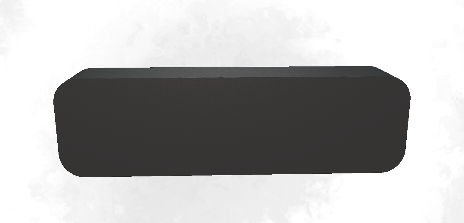
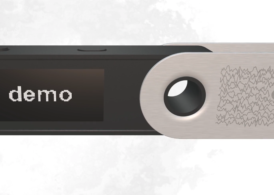
The 3D distance to a Nano S Plus
Essentially, a Nano S Plus can be rendered with a bunch of union, difference and intersection math operations. Here are the basic utilities I used:
// SHAPE PRIMITIVES:
float sdCylinder( vec3 p, vec3 c ) {
  return length(p.xz-c.xy)-c.z;
}
float sdCappedCylinder( vec3 p, float h, float r ) {
  vec2 d = abs(vec2(length(p.xz),p.y)) - vec2(h,r);
  return min(max(d.x,d.y),0.0) + length(max(d,0.0));
}
float sdBox( vec3 p, vec3 b ) {
  vec3 q = abs(p) - b;
  return length(max(q,0.0)) + min(max(q.x,max(q.y,q.z)),0.0);
}
float sdBox2(in vec2 p, in vec2 b) {
  vec2 d = abs(p) - b;
  return length(max(d, vec2(0))) + min(max(d.x, d.y), 0.0);
}
float sdBoxRoundZ(vec3 p, vec3 b, float r) {
  return max(sdBox2(p.xy, b.xy-r)-r, abs(p.z)-b.z);
}
// SHAPE OPERATIONS:
float fOpUnionRound(float a, float b, float r) {
  vec2 u = max(vec2(r - a,r - b), vec2(0));
  return max(r, min (a, b)) - length(u);
}
float fOpIntersectionRound(float a, float b, float r) {
  vec2 u = max(vec2(r + a,r + b), vec2(0));
  return min(-r, max (a, b)) + length(u);
}
float fOpDifferenceRound (float a, float b, float r) {
  return fOpIntersectionRound(a, -b, r);
}
float opSmoothSubtraction( float d1, float d2, float k ) {
  float h = clamp( 0.5 - 0.5*(d2+d1)/k, 0.0, 1.0 );
  return mix( d2, -d1, h ) + k*h*(1.0-h);
}
void pR(inout vec2 p, float a) {
  p = cos(a)*p + sin(a)*vec2(p.y, -p.x);
}
This code might seems complex, but it's relatively simple primitives, some are from this great article: https://iquilezles.org/www/articles/distfunctions/distfunctions.htm
With these utilities, I have developed that function called sdLedgerNanoSPlus, that implements the distance to a Nano S Plus:
HIT sdLedgerNanoSPlus (vec3 p, float rot)
Knowing the "space distance to an object" allows to use a raymarching algorithm to render it in 3D.
The function takes two parameters p and rot:
pis the 3D point from which to evaluate the distance. If the Nano S Plus is at 1 meter away from the Nano S Plus, it must return a value of 1 meter. as simple as this.rotallows for me to control the rotation of the swivel, so it can be animated from the caller.
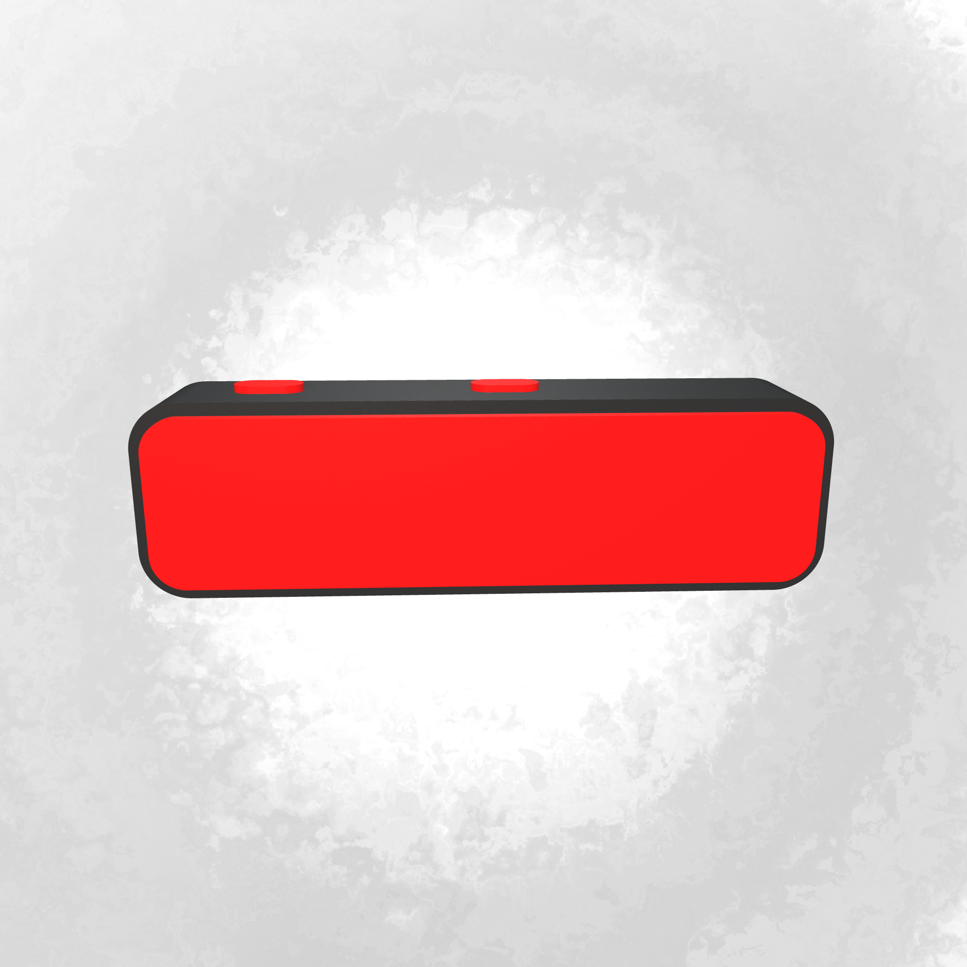
The function returns one HIT value. HIT is a simple alias to vec2, which actually allows me to return a tuple of two values: (distance, material). On top of the distance, I need to track what is the "closest material". Basically answering the question: from the point p what is the part of the Nano S Plus that is the closest? For instance, the swivel, the plastic part, the screen,...
I was able to take precise measurements from some wireframes of the actual device and tried to make it as close as possible, transposed into code.
This is probably a lot of code to digest, but here is its implementation:
HIT sdLedgerNanoSPlus (vec3 p, float rot) {
  float btn = sdBoxRoundZ(
    vec3(abs(p.x - 0.18) - 0.22, p.z, p.y - 0.155),
    vec3(0.06, 0.03, 0.04), 0.03);
  float case2d = sdBox2(p.xy, vec2(0.624, 0.174)-0.08)-0.08;
  float swivel_hook = sdCylinder(p.xzy, vec3(-0.44, 0.0, 0.074));
  HIT s = HIT(max(
    min(
      opSmoothSubtraction(
            min(
          max(case2d+0.015, abs(p.z+0.12)-0.015), // main casing carving
          btn-0.004 // btns carving
        ),
        max(case2d, abs(p.z)-0.101) - 0.01, // main casing
        0.008
      ),
      min(
        btn,
        max(swivel_hook-0.015, abs(p.z)-0.12) // plastic in the casing for the swivel
      )
    ),
    -swivel_hook // carve the swivel hook out
  ), 2.05);
  // screen
  float screen2 = sdBox2(p.xy - vec2(0.18, 0.), vec2(0.27, 0.12));
  s = opU(s, HIT(max(s.x, screen2), 2.1));
  // swivel
  p.x += 0.04;
  p.x += 0.4;
  pR(p.xy, rot);
  p.x -= 0.4;
  float w = 0.54;
  float x = p.x + 0.8;
  float z = abs(p.z) - 0.12;
  float swivel_radius = 0.192;
  float swivel_metal_width = 0.006;
  float rounding = 0.003;
  float swivel = opSmoothSubtraction(
    sdCylinder(p.xzy, vec3(-0.4, 0.0, 0.08)), // carved
    min(
      sdCappedCylinder(vec3(p.y, z, x - 0.4), swivel_radius, swivel_metal_width),
      sdBox(vec3(x - 0.41 + w, p.y, z), vec3(w, swivel_radius, swivel_metal_width))
    )-rounding,
    0.04
  );
  // metal to close the swivel end
  swivel = fOpUnionRound(swivel,
    sdBox(vec3(x + 0.135 + w, p.y, p.z), vec3(swivel_metal_width, swivel_radius, 0.123))
  ,0.01);
  noiseMetal = fbm(vec2(40.0, 1000.) * p.xy);
  vec2 coord = fract(vec2(1.0, -3.0) * p.xy + vec2(0.5));
  vec4 mt = texture2D(metalText, coord);
  float t = mix(0., grayscale(mt.rgb),mt.a * step(p.z, 0.) * step(p.x, -0.5) * step(abs(p.y), 0.16));
  float swivelM = 2.2 + t;
  s = opU(s, HIT(swivel, swivelM));
  return s;
}
To visualize it more, I've animated the code to make it show the different steps union and difference operations:
But let's try to dive into more details and tricks.
The main casing
The first part of the function is making the plastic casing:
float btn = sdBoxRoundZ(
  vec3(abs(p.x - 0.18) - 0.22, p.z, p.y - 0.155),
  vec3(0.06, 0.03, 0.04), 0.03);
float case2d = sdBox2(p.xy, vec2(0.624, 0.174)-0.08)-0.08;
float swivel_hook = sdCylinder(p.xzy, vec3(-0.44, 0.0, 0.074));
HIT s = HIT(max(
  min(
    opSmoothSubtraction(
      min(
        max(case2d+0.015, abs(p.z+0.12)-0.015), // main casing carving
        btn-0.004 // btns carving
      ),
      max(case2d, abs(p.z)-0.101) - 0.01, // main casing
      0.008
    ),
    min(
      btn, // buttons themself
      max(swivel_hook-0.015, abs(p.z)-0.12) // plastic in the casing for the swivel
    )
  ),
  -swivel_hook // carve the swivel hook out
), 2.05);
We can see that I use a lot of min() to combine the primitives. when you apply min(A,B) between the distance of objects A and B it is essentially the distance to the union of A and B, because min returns the closest distance. so min is an union.
We can also see the use of many max() like for instance max(case2d, abs(p.z)-0.101) - 0.01 which renders a rounded box but with sharp edge on the Z axis:
max(A, B)is basically the intersection of A and B. Sadly, it's not an "exact" distance that limits the ability to bevel a tiny bit the edge. If someone have a trick to implement this shape with the exact distance, I would love to know.
max(case2d, abs(p.z)-0.101) - 0.01 is therefore made of the intersection of:
case2dis a 2D box in xy space. defined bysdBox2(p.xy, vec2(0.624, 0.174)-0.08)-0.08. The value 0.8 is removed from the box dimension but also then removed from the distance. That value is actually the border radius of the box.abs(p.z)is the distance to the Z plan.abs(p.z)-0.101is distance to a volume of the plan enlarged with a0.101padding.
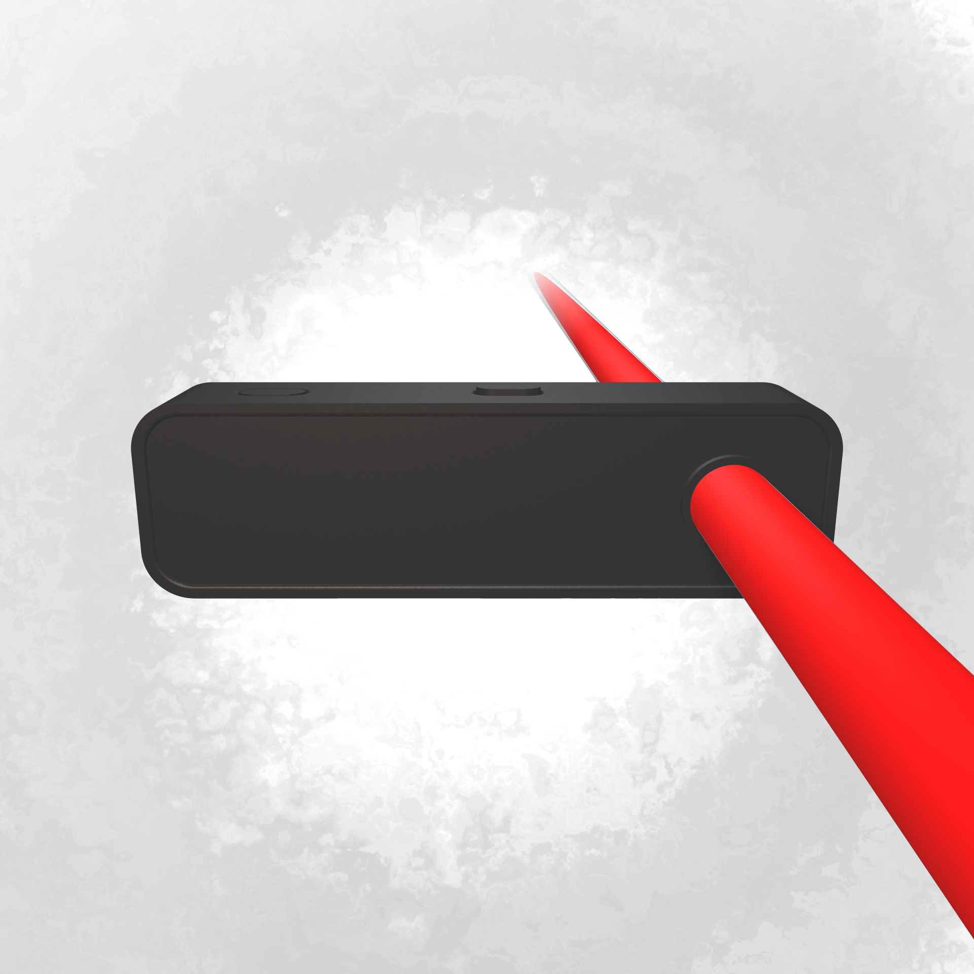
Carving out
The first operation done on the casing is to carve the part of the buttons and the inside. This is essentially done with the operation max(A, -B) (remove B from A), except here we are using a smooth difference operation to not make too "sharp" cuts.
The same technique is used on the swivel hole:
And again done on the model swivel shape:
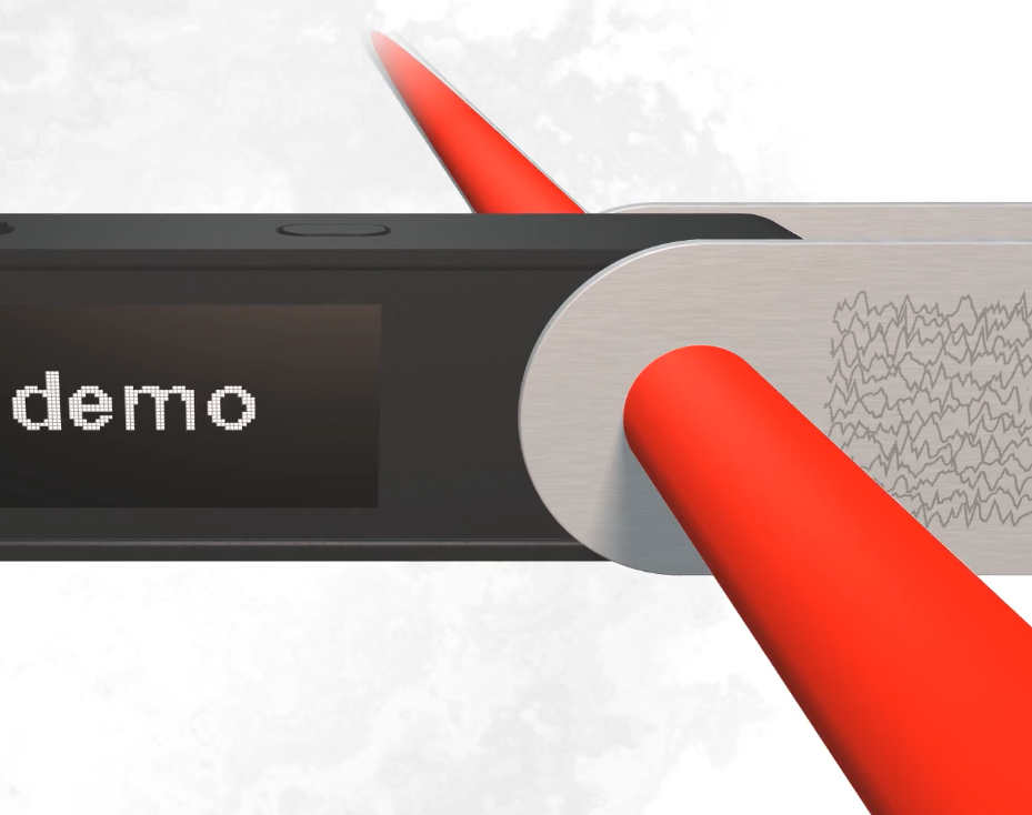
but for the swivel, it is done with a "smoothing difference", which creates the nice rounded effect in the hole:
Here is the code that do this:
opSmoothSubtraction(
  sdCylinder(p.xzy, vec3(-0.4, 0.0, 0.08)), // the carving shape is a cylinder
  min(
    sdCappedCylinder(vec3(p.y, z, x - 0.4), swivel_radius, swivel_metal_width), // circle of the swivel
    sdBox(vec3(x - 0.41 + w, p.y, z), vec3(w, swivel_radius, swivel_metal_width)) // long rectangle metal part
  )-rounding, // add a bit of rounding (bevel)
  0.04
)
and if we tweak that 0.04 value between 0.0 and 0.1, we obtain this interesting range of smoothing subtraction:
There would be so much to improve in the modelization. For instance, I couldn't figure out a simple way to make the smooth corner of the swivel metal, so I end up with this simplification which isn't perfect:
// metal to close the swivel end
swivel = fOpUnionRound(swivel,
  sdBox(vec3(x + 0.135 + w, p.y, p.z), vec3(swivel_metal_width, swivel_radius, 0.123))
,0.01);
Distance function can always be optimized and details can always be added, possibilities are infinite it's only a matter of how much hours do you want to spend on. And on my case, it was basically a weekend.
Lighting and material
There would be a lot to write about the accumulation of techniques used for the lightning. Basically there are 2-3 lights in the scene and some are casting some shadows using raymarching as well.
That video looks surprisingly so professional, I love it! The scene is just this code:
HIT map (vec3 p) {
  HIT s = HIT(10. - length(p), 0.);
  s = opU(s, HIT(length(p)-0.5, 2.05)); // sphere distance is just length(p)-radius
  return s;
}
It shows the rendering of a sphere on the plastic material. Before I talk about the materials, let's focus on the lighting.
The lighting
The general code that renders the scene is pretty straightforward:
vec3 scene(vec2 uv) {
  vec3 c = vec3(0.); // color of the pixel to set
  vec3 p = cameraP;
  vec3 dir = normalize(vec3(uv - .5, 1.)); // perspective camera
  dir = lookAt(cameraP, focusP) * dir; // camera focus on a point
  HIT hit = marcher(p, dir); // this throw camera ray and tells what points it hits (material and distance)
  vec3 n = normal(p); // this calculates the NORMAL VECTOR on the surface of the hit object
  c += lighting(hit, p, n, dir); // <= THIS IS WHERE LIGHTING IS CALCULATED
  c = mix(c, sceneBgColor, pow(smoothstep(4., 10., length(p-cameraP)), .5)); // mist on far away objects
  return c;
}
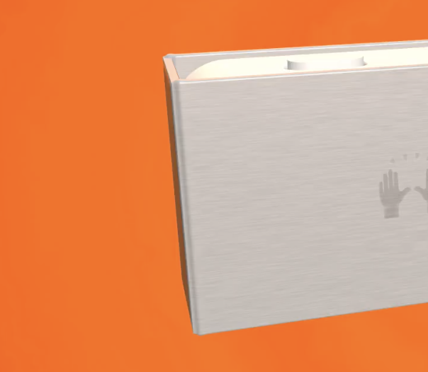
Ok, so as you can see on the previous video, we have essentially 2 lights in the scene, one blueish and one redish. They spread differently in the material to simulate a bit their different size. We however can see the user of a THIRD light, which is more in the back and will be useful to simulate the fact the background is emitting its color. This was very useful for strong background colors like orange:
This is what lighting is implementing:
vec3 lighting (HIT hit, vec3 p, vec3 n, vec3 dir) { // (code is a bit simplified from original)
  vec3 l, ldir;
  vec3 c = vec3(0.);
  l = vec3(lightPos, 1.5, -3.4);
  vec3 obj = shade(hit, p);
  ldir = normalize(l - p);
  c +=
  0.92 * vec3(0.9, 0.7, 0.6) * (
    // ambient
    0.1
    // diffuse
    + obj
      * (.5 + .5 * diffuse(p, n, l)) // half lambert
      * (0.5 + 0.5 * softshadow(p, ldir, 0.05, 5., 8.))
    + specular(n, p, hit.y, ldir, dir, 10.)
  );
  l = vec3(-lightPos, 5., -2.);
  ldir = normalize(l - p);
  c +=
  0.92 * vec3(0.3, 0.5, 0.6) * (
  // ambient
  0.1
  // diffuse
  + obj
    * (.5 + .5 * diffuse(p, n, l)) // half lambert
  + specular(n, p, hit.y, ldir, dir, 20.)
  );

  l = vec3(0., 2., 8.);
  ldir = normalize(l - p);
  c += bgLightColor * (
    obj
    * diffuse(p, n, l)
    + specular(n, p, hit.y, ldir, dir, 20.)
  );
  return c;
}
You can see the first thing done here is:
vec3 obj = shade(hit, p);
It is a very important step that ask the hit object material "give me your color". I will cover it in the Material section.
Then for each light I want to apply, you can see the same pattern:
First of all, we will put the light at a specific position in the space. For instance:
l = vec3(lightPos, 1.5, -3.4);
we calculate the actual light direction with p which is the point of interest to color.
ldir = normalize(l - p);
And then we can finally add to the object its emitted color:
  c +=
  0.92 * vec3(0.9, 0.7, 0.6) * (
    // ambient
    0.1
    // diffuse
    + obj
      * (.5 + .5 * diffuse(p, n, l)) // half lambert
      * (0.5 + 0.5 * softshadow(p, ldir, 0.05, 5., 8.))
    + specular(n, p, hit.y, ldir, dir, 10.)
  );
and there are a few components that is very inspired by the classical "ambient diffuse specular" paradigm: https://learnopengl.com/Lighting/Basic-Lighting which I recommend you to read if you want to dive more into this part.
In my case, I use half lambert technique which I find really interesting for a cartoon-ish effect https://developer.valvesoftware.com/wiki/Half_Lambert and because i don't use expensive ambient occlusion.
I also, in this light case, will use softshadow that cast a shadow toward the light direction.
specular function is an important utility that have this implementation:
float specular (vec3 n, vec3 pos, float m, vec3 ldir, vec3 dir, float p) {
  return specularStrength(m, n, pos) * pow(max(dot(dir, reflect(ldir, n)), 0.0), p);
}
note that we can have different "specular strength" for each material or even depending on the position.
The material specularStrength()
As we can see in this material, the plastic has been added some texturing.
This is implemented with a fbm noise and it is contained in the material value.
Then I had two possible ways to make it visible: either I change the color of the material OR I change the way it reflect lights in specularStrength. I've used the second option for the plastic case:
float noiseMetal;
float specularStrength (float m, vec3 n, vec3 p) {
  if (m < 2.1) {
      float v =
        n.z * fbm(600. * p.xy) +
        n.x * fbm(600. * p.yz) +
        n.y * fbm(600. * p.xz);
      return 0.4 + 0.3 * v;
  }
  if (m < 2.2) {
    return 2.0;
  }
  if (m < 4.) {
    return 0.6 - 0.5 * noiseMetal + 1. * ceil(m-2.21);
  }
  return 0.4;
}
So pretty basic stuff, I use m material value, which is a one dimension value to express all materials in. in plastic case, we are in the m < 2.1 case which have a strong noise frequency.
On the same principle, we can see it is also done for the swivel metal.
I used some trickery here because, as the swivel is moving, I had to use a global variable to set the noise value because I don't have the "local position", only the global position.
The noiseMetal is set directly from the sdLedgerNanoSPlus function with this:
noiseMetal = fbm(vec2(40.0, 1000.) * p.xy);
where p is a local position of the swivel, contextual to the rotation applied to it.
The 40/1000 implements a stretched fbm noise which nicely recreates the effect:
The material shade()
shade(hit,p) is essentially the material coloring function. It tells what color does the object reflect at a given hit position.
Here is its implementation for the whole scene (I have omitted some part that will be covered in other articles):
vec3 shade (HIT hit, vec3 p) {
  if (hit.y < 2.0) return sceneBgColor;
  if (hit.y < 4.0) {
    if (hit.y < 2.1) {
        return plasticColor;
    }
    if (hit.y < 2.2) {
      return ...SCREEN RENDERING HERE...;
    }
    // swivel metal
    return vec3(0.7 - 0.1 * noiseMetal - 0.2 * (hit.y - 2.2));
  }
  if (hit.y < 5.0) {
    return stickerColor;
  }
  return vec3(0.0);
}
So it's a simple, "give me the color of the material id number". The only trick for the noise metal was to make it a bit darker on some part to accentuate the metal effect.
The next article is going to dive into what this ...SCREEN RENDERING HERE... part is doing, and more generally how I managed to also make the screen display text from inside a shader!